I recently purchased a monitor for my home setup and was looking for a fun side project to work on. I had some spare WS2812 leds lying around and an arduino which I used for my Music controlled LEDs project. One post on r/battlestations caught my attention and I decided to mod my monitor with a ambilight. I was familiar with some software but making it work on mac os was a bit challenging. Before I explain how I accomplished that here's a video of the ambilight in action.
Hardware
This is a list of hardware components used and the links to buy them. Note that I bought most of the electronic components from China using banggood.in as they were considerably cheaper. You can source them locally if you dont want to wait for the components.- WS2812 LED strip: I found this particular brand to be the cheapest and best suited for my purpose. The strip comes with a controller with built-in effects and can be controlled by a remote which is included. My LED controller broke within a few days though but it's a nice addition if you wish them as stand alone lighting
- Arduino UNO: I brought this one because I wanted to learn how to use arduino. You can probably work with Arduino Nano if you want some thing cheaper
- Wires and stuff: This is a generic set of wires for all my hobby projects. This also includes and assortment of electrical components like resistors, capacitors etc.
Setup
Wiring up the LEDs
Wiring up the arduino to the LEDs is pretty simple. The WS2812 LED strip has 3 input pins.- The +5V is the power input. Connect this pin to Arduinos 5V pin, alternatively you can use an external power supply if you wish to power more LEDs.
- Connect the GND pin to the GND pin on the arduino or if you have an external power supply connect this pin to its ground terminal
- The Data pin is the one which informs the LED which colour to display and which LED to light up. Connect it to any one of the Digital IN pins, I used pin 9 for my setup.
Testing the LED's with Arduino
Since we have already wired up the arduino and the LED strip we can test the LED's using the FastLED library. Download it from arduino IDE and run some sample code. To check follow this steps- Go to Tools menu and select manage libraries. Search for FastLED library and install it.
- Go to Files and select any file like Blink from the FastLed submenu
- This will open up the sketch in the text editor. Select the number of LEDs and the data pin correctly
- Upload the sketch to arduino and the LEDs should light up.
Installing Hyperion
Once we have made sure the LEDs work we start with the installation of Hyperion software. This software makes it easy to run the LED ambilight based on the colours being displayed on the screen. The software can be easily installed on Linux but takes some tweaking to run on MacOS. Follow the instructions provided here or clone my forked repo directly from here after copying the files from repo follow these steps.
- Go to the directory and create a new directory named build
- Run the following command
cmake -DENABLE_DISPMANX=OFF -DENABLE_SPIDEV=OFF -DENABLE_V4L2=OFF -DENABLE_OSX=ON .. - Run this command next
make -j $(nproc) - Clean up using
strip bin/* - Add both binaries to /bin
sudo cp ./bin/hyperion-remote /usr/bin/ ;
          sudo cp ./bin/hyperiond /usr/bin/
Hyperion works with different devices like Adalight, Philips Hue etc. What we want to do is emulate the AdaLight device using Arduino. This can be done with the help of an arduino sketch from here. Flash this sketch to your arduino device setting the correct DATA PIN (9 in our case) and BAUD RATE.
Applying LEDs to Monitor
Apply LEDs along the edge of your monitor. Make sure you count the number of LEDs along each side. I was reusing a LED strip I had cut previously so I had to do a little bit of Soldering, try to avoid soldering strips because it's really hard. If you still want to do it search for the video on youtube to get idea on how to do it. WS2812 can be directly applied by removing the sticker on the back. The glue holds well and you should face no problems, I had to use a double sided tape because my adhesive was all worn out. Once you've done that you can connect the terminals as we discussed earlier using the wires we got and the connector on the LED strip.
This Picture might give you idea (I have used double sided tape) 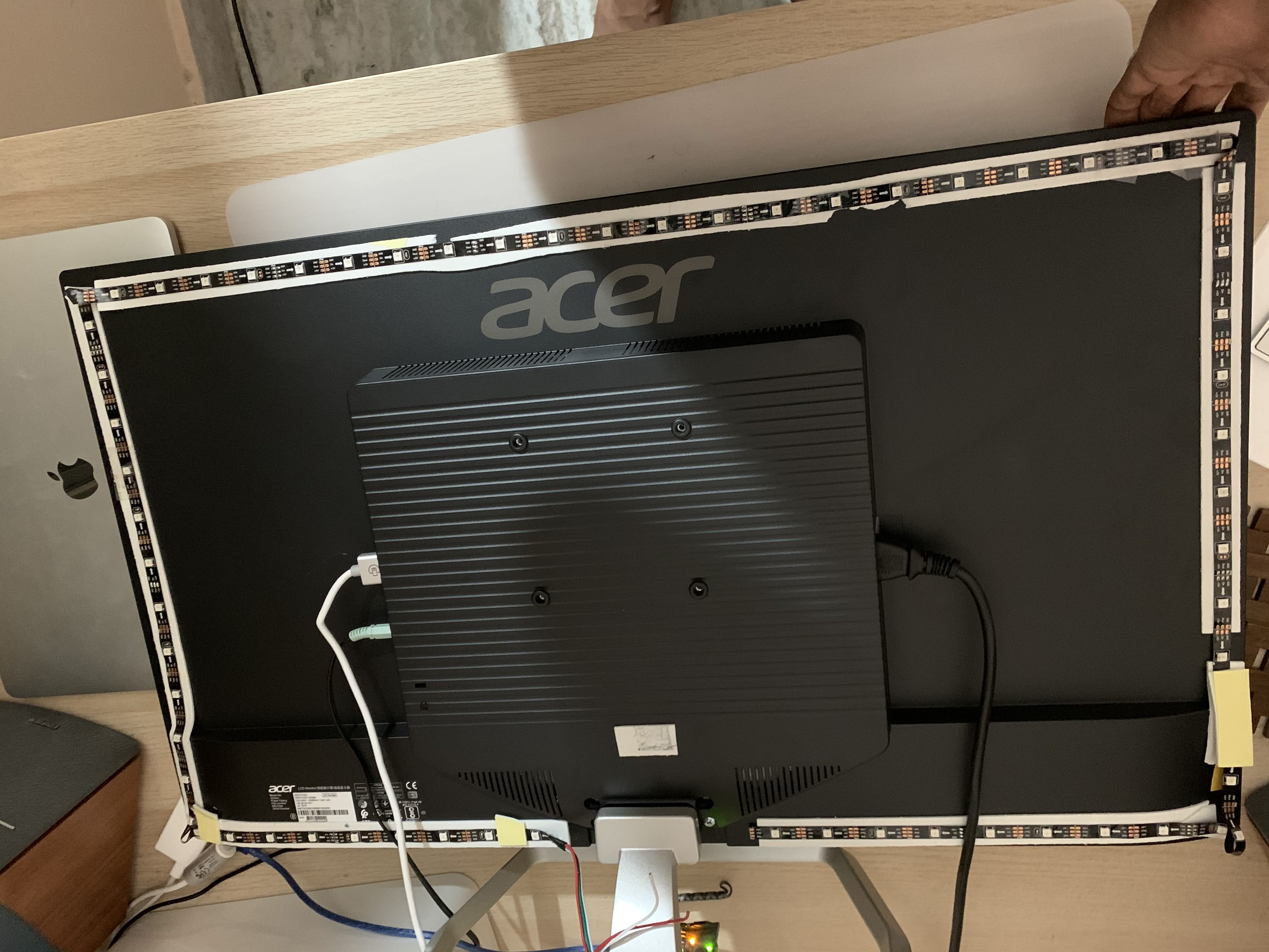
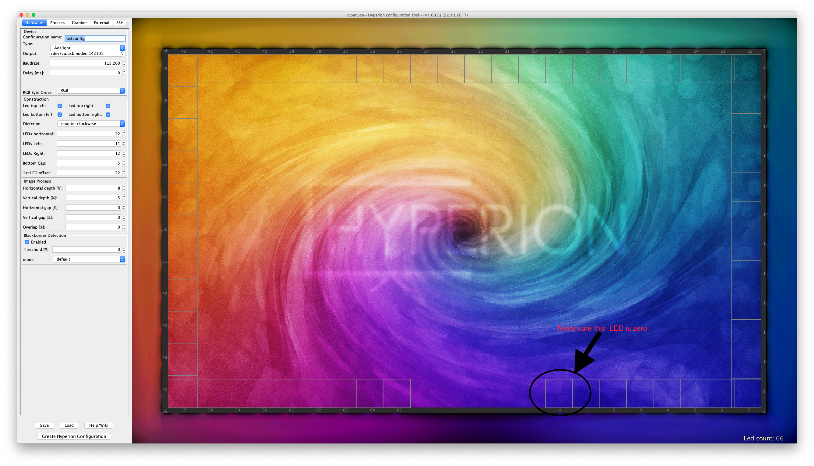
Generate configuration file using Hypercon
Download Hypercon which is a GUI tool to generate Hypeion Config file. Hyperion config file tells arduino which LEDs correspond to which part of of screen and their relative positions. Hypercon makes it very easy and intuitive to generate a config file for your configuration.
- Download the HyperCon JAR from here
- Open it and insert the Output Port correctly. The port name can be easily found out from arduino IDE (tools->port)
- Select device type as AdaLight
- Enter Baud rate similar to one entered in Arduino sketch (115,200 works and Mac OS doesn't allow custom Baud rates)
- Fill up the construction section according to how you've applied the LEDs. Choose the Direction and First LED offset such that they correspond to the direction you've applied
- Enter the horizontal and vertical LEDs and dont forget to fill the Bottom gap
- If you've folded the strip at corners like me select the LED checkboxes at the top
- I haven't messed with the other parameters but I found that these defaults work very well
- Save this file as a config file by clicking the Create Hyperion Configuration button and save the file somewhere
Run the Ambilight!
Now since everything is setup we should be able to run our ambilight. Start the hyperion daemon with the configuration file we have generated using this command
hyperiond <location-of-config-file> References
This post is heavily inspired by this blog which uses raspberrypi to accomplish the same task. Do give it a look if you want in detail treatment of this whole project. I've kept this mostly simple and easy to implement. For more information feel free to contact me at my email.Additional Tweaks (November 1 2019)
So I had to re-configure the the Ambilight after coming back from home due to some issues. This time I decided to explore some of the other settings in HyperCon. The two settings which I feel are important are colour calibration and black edge detection. I'll explain them in detail below.
- Every LED has some variation in the way they are calibrated, and this may cause some issues with our project. While watching some movies I noticed that white background cause the LEDs to emit reddish colour instead of pure white colour. So after some googling I found a very helpful guide on Hyperion forums which helped me calibrate the white levels on my monitor. One jugaad I had to do was to edit the configuration file directly from command line as I haven't activated SSH for the ambilight (which is recommended in the guide). If you want slightly better colour reproduction check out this guide
- The other issue I faced was with movies in aspect ratios other than 16:9 , The black bar at the top and bottom would render the backlight completely useless. I started searching for a fix for this issue and the fix was pretty simple. In the Hardware Tab in HyperCon just enable Black Border Detection and set the threshold to something sensible 13% worked well in my case but for people who want to get the best results refer here for optimal setting. One thing to note is just enabling the BlackBorder detector doesn't work as the default threshold is set to 0, set it to non zero value and it should work